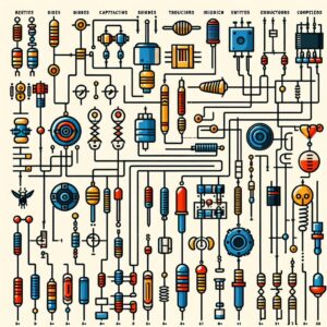
Common Electrical Components and Their Symbols
A resistor is a fundamental component designed to provide a specified resistance in an electrical circuit. The symbol for a resistor is a simple, uncomplicated shape. In international circuits, you might encounter a small rectangle as the symbol for a resistor. In American circuits, a series of peaks and valleys – reminiscent of an undulating line – represents the resistor. The simplicity of the symbol makes it easily recognizable and straightforward to draw. Variability in resistor types, such as potentiometers (variable resistors), is indicated by a straight line cutting through the zigzag or rectangle and ending in an arrow.
Capacitors store electrical energy temporarily and can release it into the circuit when required. The symbol for a capacitor is depicted by two parallel lines facing each other, reflecting the two plates of a capacitor separated by an insulating material. If the capacitor is polarized, meaning that current can flow through it in only one direction, the symbol changes slightly. One of the parallel lines becomes curved, explicitly indicating the correct orientation in the circuit.
An inductor consists of a coil of wire that generates a magnetic field as current passes through it. The symbol for an inductor mirrors this construction, shown as a series of loops or curved lines. This visualizes the coiled wire that forms the inductor’s intended shape.
Diodes are components that allow current to flow in only one direction. They act as one-way streets for electricity. The symbol for a diode consists of a triangle contiguous with a line. The direction of the triangle points to the permitted direction of current flow, resembling an arrow that indicates its unidirectional nature.
Transistors are versatile components used to amplify or switch electronic signals. Their symbols show three lines that represent the three leads: emitter, base, and collector. There are two main types of transistors, namely NPN and PNP, and their symbols differ to reflect the direction in which current moves through them. The NPN transistor symbol has the emitter arrow pointing away from the base, while PNP has it pointing towards it.
Switches are devices that can open or interrupt the flow of electrical current in a circuit. The symbol for a switch appears as a break in a line, indicating that the current path can be disconnected. This gap can be shown in an open or closed position, demonstrating the function of controlling the flow of electricity.
Batteries provide the electrical energy to power circuits. The symbol for a battery is a series of long and short parallel lines. These lines represent the positive and negative terminals and cells within a battery. The long line corresponds with the positive terminal, the short line with the negative terminal.
The ground, or earth, is a reference point in an electrical circuit that represents the zero-voltage level. In schematic diagrams, various symbols might represent ground. The most common ground symbol is a vertical line branching into three smaller horizontal lines, each successively shorter, vaguely representing the stratification of the ground.
Reading and Interpreting Circuit Diagrams
When beginning to read a circuit diagram, it’s important to approach it systematically. One should start at the power source, denoted by a specific symbol such as a pair of short and long parallel lines indicating a battery, and trace the route that the current takes through the circuit.
 The flow guides the interpretation of how the components interact and what role they play. The direction of the current is indicated on the diagram and is assumed to flow from the positive to the negative terminal of the power source in conventional terms.
Each component symbol is accompanied by a value that indicates its properties, such as resistance in ohms or capacitance in farads. These values are necessary to understand the electrical characteristics of the circuit and are important for both construction and troubleshooting.
Tracing paths and connections between components involves looking for lines that connect different components and understanding if they are connected in series or parallel, which affects the overall behavior of the circuit.
The points where the connections join are referred to as nodes. Identifying node points helps in comprehending the circuit’s complexity. These nodes are necessary when it comes to breaking down a circuit into more manageable parts for analysis.
Understanding elements such as switches and relays placement and operation is important for comprehending how the circuit responds to different conditions. Interpreting these elements accurately is important for analyzing or constructing a circuit’s functionality.
Power rails, marked with ‘+’ for positive voltage and ‘-‘ for ground or negative voltage, provide a visual cue of the voltage levels throughout the circuit. Recognizing these symbols and their relationships to other components is important for understanding the overall power scheme.
Annotations, notes, and other additional information on the circuit diagram can offer insights into the designer’s intentions, operating conditions, or specific instructions for elements that might not be outright apparent.
The Role of Circuit Diagrams in Electrical Projects
For individuals creating a circuit, the diagram is the guide that illustrates where each component should be placed and how they are connected. Without this roadmap, constructing an electrical device would be significantly more difficult and prone to error. It is the precise nature of these diagrams that allows for consistency and repeatability in building electronic devices or systems.
Circuit diagrams allow for a clear and concise description of an electrical system’s workings, which is essential for the coordination of complex projects. These diagrams ensure that everyone involved has a shared understanding of how the system functions, which components it includes, and what the outcome should be.
When designing an electrical system, engineers use circuit diagrams to plan the layout and components necessary for the desired function. They enable engineers to predict how different configurations will behave without the need for physical prototypes. By altering a design on paper (or in a digital schematic), designers can optimize performance and identify potential issues before they reach the manufacturing phase.
When an electrical device malfunctions, technicians can refer to the circuit diagram to understand the intended operation and compare it against the device’s actual behavior. By following the diagram, they can isolate individual components and pathways to pinpoint the source of a problem, which aids in effective diagnosis and repair.
Circuit diagrams act as a documentation tool that provides invaluable information for future reference. Over the lifespan of an electrical system or device, maintenance is required, and modifications might be made. Having a detailed circuit diagram ensures that such interventions can be recorded and understood by anyone who works on the system thereafter, ensuring the longevity and reliability of the electrical system.